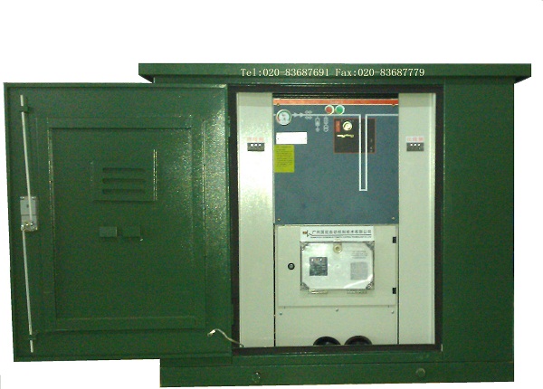
落地共箱式SF6(六氟化硫)气体全绝缘全密封智能分界开关柜NKXGN16-12/24/35本体部分介绍(断路器)
NKXGN16-12/24/35箱型固定式交流充气金属封闭开关设备
( 二) .1概述
NKXGN16-12/24/35箱型固定式交流充气金属封闭开关设备
(简称”SF6充气环网柜)是具有高可靠性的免维护小型化开关柜,
产品适用于三相交流50Hz,电压为3-12/24/35KV环网供电或辐射供电系统;产品所有高压带电部件,包括负荷开关,断路器,接地开关,一次母线等均密封在充有SF6气体的不锈钢箱体中,进出线采用全密封的肘形电缆插头,受环境影响少,特别适用于二次配电站,小型开闭所,工矿企业,城市居民小区,机场,铁路,遂道,高层建筑等配电系统中作为接受和分配电能之用。
本系列环网柜符合
GB/T11022-1999<<高压开关设备和控制设备标准的共用技术要求>>,
GB3804-2004<3.6KV-40.5KV高压交流负荷开关>>,
GB16926-1997<<高压交流负荷开关-熔断器>>
GB1984-2003<<高压交流断路器>>
GB-1985-2004<<高压交流隔离开关和接地开关>>,
DL/T404-1997 <<户内交流高压开关柜订货技术条件>>,
DL/T791-2001<<户内交流充气式开关柜选用导则>>等标准,
General
NKXGN16-12/24/35- series fixed type indoor AC metal clad switchgear (SF6 RMU Abbreviation). one of minimized switchgear with the character of excellence reliability and maintenance free ,is a new product self –developed by R&D of our group based on the years experience in R&D and fabrication on products and on the advance technology
The product is suitable for AC 3 to 12/24/35KV power distribution system with configuration either ring
or radiant.. Its all live part including LBS,CB, ES and primary busbar are sealed in the tank made of
stainless steel and the elbow –shape cable connectors and adopted for the incoming or out-going, that
leds it is suitable for use in the bad ambient condition and relatively restricted space ,just like in
pre-fabricated substation, underground substation, industrial and mining enterprises or in high humidity
and heavy pollution area.
The series of RMU is compliance with the following standards and its service life is mord than 20 years under normal ambient condition.
GB/T1022-1999 <<Common specifications for high-voltage switchgear and controlgear standars>>
IEC 694:1996 Common specifications for high-voltage switchgear and controlgear standards EQV
GB3804-2004 <<Alternating current high voltage load-breaker>>
(IEC 60265-1/FDIS: 1997 high voltage switchgear part 1:Swiches for rated voltage above 1KV and less than 52KV .MOD
GB/T1984-2003 <<Alternating current high –voltage circuit-breaker>>
(IEC 62271-100: 2001 high –voltage switchgear and controlgear part 100: high-voltage alternating-current circuit-breakers .MOD)
GB/T1984-2004<<High-voltage alternating-current disconnectors and earthing Switches>>
(IEC 62271-100: 2002 high –voltage alternating-current disconnectors and earthing switches .MOD)
DL/T404-1997<<Indoor AC high voltage switchgear>>
(IEC298:1990 A.C metal-enclosed switchgear and controlgear for rated voltages above 1KV and up to including 52KV .EQV)
DL/.T791-2001<<Specifications of A.C. HV gas-filled switchgear panel >>
(IEC420:1990 high-voltage alternating current switch-fuse combination and IEC 517-1990
Gas-insulated metal-enclosed switchgear for rated voltage of 72.5KV and above :MOD)
Product code of manufacturer
NK(XGN口-35)口
NK产品企业代号
X箱型 Cubicle Type
G固定式 Fixde Type
N户内 Indoor
口设计序号 Design Series
12/24/35额定电压kV Rated Voltage
口组合方案(V、F、C、D)
Combination Scheme
V: 真空断路器单元
V: VCB unit
F: 负荷开关熔断器组合单元
F : LBS-Fuse combination unit
C: 负荷开关单元
C: LBS unit
D: 直接进出线单元
D: in & Out Directly unit
( 二) .2正常使用条件及技术参数
环境温度:最高+40℃, 不低于-25℃
环境湿度:相地湿度日平均不大于95%,月平均不大于90%
海拨高度:不超过2000米
地震烈度;不超过8度
没有火灾、爆炸危险、化学腐蚀及剧烈震动场所
Normal service conditions
Ambient temperature: highest + 40℃, lowest in - 25℃
Environmental humidity: average daily do not more than 95%, average monthly do not more than 90%
Altitude :Not more than 1000 meters
Seismic intensity : Not more than 8 degrees
No fire and explosion danger, no chemical corrosion and violent vibration places
|
序号
RF
|
环网柜主要技术参数
名称 Parameter
|
单位
Unit
|
参数Value
|
|
|
|
|
C mod
|
F mod
|
Vmod
|
D mod
|
|
1
|
额定电压 Rated voltage
|
KV
|
12
|
|
2
|
额定
绝缘水平
Rated insulating level
|
工频耐压(1min)
Power
frequency withstand voltage(1min.)
|
相间,相对地
Between phase,phase to earth
|
KV
|
42
|
42
|
42
|
42
|
|
3
|
|
|
断口Across the opened break
|
KV
|
48
|
48
|
48
|
48
|
|
4
|
|
雷电冲击耐压
(峰值)
lightning withstand voltage(peak)
|
相间,相对地
Between phase,phase to earth
|
KV
|
75
|
75
|
75
|
75
|
|
5
|
|
|
断口
Across the opened break
|
KV
|
85
|
85
|
85
|
85
|
|
6
|
额定频率 Rated frequency
|
Hz
|
50
|
|
7
|
额定电流 Rated current
|
A
|
630
|
100
|
630
|
630
|
|
8
|
额定转移电流 Rated transfer current
|
A
|
|
1500
|
|
|
|
9
|
额定短路开断电流 Rated short circuit breaking current
|
KA
|
|
20
|
20
|
|
|
10
|
额定短路关合电流 Rated making current
|
KA
|
50
|
50
|
50
|
|
|
11
|
额定短时耐受电流(负荷/接地开关)
Rated shortime withstand current (LBS/ES)
|
KA
|
20
|
|
20
|
20
|
|
12
|
额定短路持续时间(负荷/接地开关)
Rated short circuit duration (LBS/ES)
|
s
|
3
|
|
3
|
3
|
|
13
|
额定峰值耐受电流(负荷/接地开关)
Rated peak withstand current(LBS/ES)
|
KA
|
50
|
|
50
|
50
|
|
14
|
额定短路关合电流 (接地开关)Rated making current(ES)
|
KA
|
50
|
|
|
15
|
额定机械寿命(负荷开关)Rated mechanincal life(LBS)
|
次times
|
1000
|
1000 (VCB)
(断路器)
|
|
16
|
额定机械寿命(接地开关)Rated mechanincal life(ES)
|
次times
|
1000
|
|
|
17
|
额定
开断电流
Rated breaking current
|
闭环开断电流Breaking current of close loop
|
A
|
630
|
|
|
|
|
|
|
有功负载开断电流
Breaking current of active power
|
A
|
630
|
|
|
|
|
|
|
电缆充电开断电流
Breaking current of cable charging
|
A
|
40
|
|
|
|
|
18
|
撞击脱扣 Strike trip
|
次times
|
|
100
|
|
|
|
19
|
二次回路1min工频耐压
Power frequency withstand voltage on secondary circuit(1 min.)
|
KV
|
2
|
|
21
|
负荷开关短路关合电流操作循环次数
Operation cycle times for short circuit making current of LBS
|
次
times
|
3(E2级) 3(E2 class)
|
|
22
|
SF6气体额定压力(20℃表压)
Rated pressure of SF6 gas (at 20℃,gauge)
|
Mpa
|
0.03
|
|
23
|
柜体及外壳防护等级
Protetcion class of cubicle body and the shell
|
|
IP3X
|
|
|
密封气室防护等级Protetcion class of gas sealing chamber
|
|
IP67
|
|
序号
RF
|
环网柜主要技术参数
名称 Parameter
|
单位
Unit
|
参数Value
|
|
|
|
|
C mod
|
F mod
|
Vmod
|
D mod
|
|
1
|
额定电压 Rated voltage
|
KV
|
24
|
|
2
|
额定
绝缘水平
Rated insulating level
|
工频耐压(1min)
Power
frequency withstand voltage(1min.)
|
相间,相对地
Between phase,phase to earth
|
KV
|
64
|
64
|
64
|
64
|
|
3
|
|
|
断口Across the opened break
|
KV
|
79
|
79
|
79
|
79
|
|
4
|
|
雷电冲击耐压
(峰值)
lightning withstand voltage(peak)
|
相间,相对地
Between phase,phase to earth
|
KV
|
125
|
125
|
125
|
125
|
|
5
|
|
|
断口
Across the opened break
|
KV
|
145
|
145
|
145
|
145
|
|
6
|
额定频率 Rated frequency
|
Hz
|
50
|
|
7
|
额定电流 Rated current
|
A
|
630
|
100
|
630
|
630
|
|
8
|
额定转移电流 Rated transfer current
|
A
|
|
1500
|
|
|
|
9
|
额定短路开断电流 Rated short circuit breaking current
|
KA
|
|
20
|
20
|
|
|
10
|
额定短路关合电流 Rated making current
|
KA
|
50
|
50
|
50
|
|
|
11
|
额定短时耐受电流(负荷/接地开关)
Rated shortime withstand current (LBS/ES)
|
KA
|
20
|
|
20
|
20
|
|
12
|
额定短路持续时间(负荷/接地开关)
Rated short circuit duration (LBS/ES)
|
s
|
3
|
|
3
|
3
|
|
13
|
额定峰值耐受电流(负荷/接地开关)
Rated peak withstand current(LBS/ES)
|
KA
|
50
|
|
50
|
50
|
|
14
|
额定短路关合电流 (接地开关)Rated making current(ES)
|
KA
|
50
|
|
|
15
|
额定机械寿命(负荷开关)Rated mechanincal life(LBS)
|
次times
|
1000
|
1000 (VCB)
(断路器)
|
|
16
|
额定机械寿命(接地开关)Rated mechanincal life(ES)
|
次times
|
1000
|
|
|
17
|
额定
开断电流
Rated breaking current
|
闭环开断电流Breaking current of close loop
|
A
|
630
|
|
|
|
|
|
|
有功负载开断电流
Breaking current of active power
|
A
|
630
|
|
|
|
|
|
|
电缆充电开断电流
Breaking current of cable charging
|
A
|
40
|
|
|
|
|
18
|
撞击脱扣 Strike trip
|
次times
|
|
100
|
|
|
|
19
|
二次回路1min工频耐压
Power frequency withstand voltage on secondary circuit(1 min.)
|
KV
|
2
|
|
21
|
负荷开关短路关合电流操作循环次数
Operation cycle times for short circuit making current of LBS
|
次
times
|
3(E2级) 3(E2 class)
|
|
22
|
SF6气体额定压力(20℃表压)
Rated pressure of SF6 gas (at 20℃,gauge)
|
Mpa
|
0.03
|
|
23
|
柜体及外壳防护等级
Protetcion class of cubicle body and the shell
|
|
IP3X
|
|
|
密封气室防护等级Protetcion class of gas sealing chamber
|
|
IP67
|
|
序号
RF
|
环网柜主要技术参数
名称 Parameter
|
单位
Unit
|
参数Value
|
|
|
|
|
C mod
|
F mod
|
Vmod
|
D mod
|
|
1
|
额定电压 Rated voltage
|
KV
|
35
|
|
2
|
额定
绝缘水平
Rated insulating level
|
工频耐压(1min)
Power
frequency withstand voltage(1min.)
|
相间,相对地
Between phase,phase to earth
|
KV
|
95
|
95
|
95
|
95
|
|
3
|
|
|
断口Across the opened break
|
KV
|
110
|
110
|
110
|
110
|
|
4
|
|
雷电冲击耐压
(峰值)
lightning withstand voltage(peak)
|
相间,相对地
Between phase,phase to earth
|
KV
|
185
|
185
|
185
|
185
|
|
5
|
|
|
断口
Across the opened break
|
KV
|
215
|
215
|
215
|
215
|
|
6
|
额定频率 Rated frequency
|
Hz
|
50
|
|
7
|
额定电流 Rated current
|
A
|
630
|
100
|
630
|
630
|
|
8
|
额定转移电流 Rated transfer current
|
A
|
|
1500
|
|
|
|
9
|
额定短路开断电流 Rated short circuit breaking current
|
KA
|
|
20
|
20
|
|
|
10
|
额定短路关合电流 Rated making current
|
KA
|
50
|
50
|
50
|
|
|
11
|
额定短时耐受电流(负荷/接地开关)
Rated shortime withstand current (LBS/ES)
|
KA
|
20
|
|
20
|
20
|
|
12
|
额定短路持续时间(负荷/接地开关)
Rated short circuit duration (LBS/ES)
|
s
|
3
|
|
3
|
3
|
|
13
|
额定峰值耐受电流(负荷/接地开关)
Rated peak withstand current(LBS/ES)
|
KA
|
50
|
|
50
|
50
|
|
14
|
额定短路关合电流 (接地开关)Rated making current(ES)
|
KA
|
50
|
|
|
15
|
额定机械寿命(负荷开关)Rated mechanincal life(LBS)
|
次times
|
1000
|
1000 (VCB)
(断路器)
|
|
16
|
额定机械寿命(接地开关)Rated mechanincal life(ES)
|
次times
|
1000
|
|
|
17
|
额定
开断电流
Rated breaking current
|
闭环开断电流Breaking current of close loop
|
A
|
630
|
|
|
|
|
|
|
有功负载开断电流
Breaking current of active power
|
A
|
630
|
|
|
|
|
|
|
电缆充电开断电流
Breaking current of cable charging
|
A
|
40
|
|
|
|
|
18
|
撞击脱扣 Strike trip
|
次times
|
|
100
|
|
|
|
19
|
二次回路1min工频耐压
Power frequency withstand voltage on secondary circuit(1 min.)
|
KV
|
2
|
|
21
|
负荷开关短路关合电流操作循环次数
Operation cycle times for short circuit making current of LBS
|
次
times
|
3(E2级) 3(E2 class)
|
|
22
|
SF6气体额定压力(20℃表压)
Rated pressure of SF6 gas (at 20℃gauge)
|
Mpa
|
0.03
|
|
23
|
柜体及外壳防护等级
Protetcion class of cubicle body and the shell
|
|
IP3X
|
|
|
密封气室防护等级Protetcion class of gas sealing chamber
|
|
IP67
|
结构示意图 Structure diagram
本柜由不锈钢密封气箱和操作机构室、熔断器室、电缆室等组成,整个柜体无焊接部位,并通过螺栓与气箱装配成一体。
The cubicle consists of a stainless steel gas sealed tank and operating mechanism chamber, fuse chamber, and cable chamber ,etc.
All chamber arE joined together with gas sealed tank by bolts, rather than by weldeing .
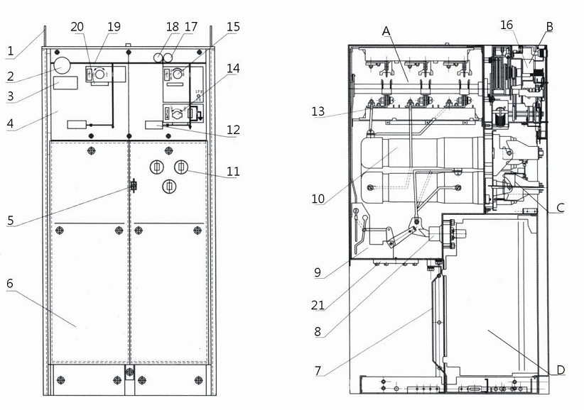
开关柜外形及基本结构
A开关-母线室 B 操作机构室 C 熔断器室 D 电缆室
1 吊环 2 压力表 3铭牌 4 面板 5 熔断器动作指示标志 6 电缆室 7 接地母排
8 进出线绝缘套管 9 接地开关 10 熔断器密封仓 11 熔断器室 12 电压指示器
13母线 14 接地开关操作孔 15 负荷开关操作孔 16 操作机构 17 合闸按钮
18 分闸按钮 19 模拟线路图 20 面板上的挂锁装置 21 泄压装置
开关母线室 LBS-Busbar chamber
●不锈钢密封气箱(除熔断器外),构成了开关母线室。
The LBS-busbar chamber is formed by Stainless steel gas sealed tank besides fuses.
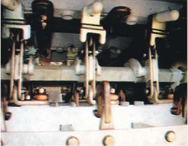
三相负荷开关作为一个整体部件调试完后装入气箱内,开关结构为旋转式三工位,兼备隔离和接地功能。开关静触头上装有金属栅栏,且呈曲线型,增强灭弧时去游离效果。
Three-phase LBS is fixed in gas sealed tank as a compiete component after assembly and adjustment. The structure of LBS is of rotary type three positions one ,it is with disconnection and isolation function.There are matel arc-barries on top of static contacts arrayed in curve to enhance the dis-extrication effect during are-extinguishing.

●为优化气箱内的电场分布,主母线设计为带R5圆角的矩形铜排,环网回路母线和变压器回路母线分别为Φ20mm和Φ10mm的铜棒,对可能引起尖端放电的部位,如母线连接及固定处,均装设了金属屏蔽罩,用以均匀电场,提高绝缘强度。
For optimize the electric field inside tank , the rectangle shape main busbars are designed to be with R5 fillet,the loop busbar of ring net and transformer adopt copper rods with diameter of Φ20mm and Φ10mm separately, the metal shield covers are used in somewhtere the point or marginal discharge may cause just like the connections and the fixed of busbar, for equalizing the electric field therefore rising up the insulation strength
操作机构室 Operating mechanism chamber
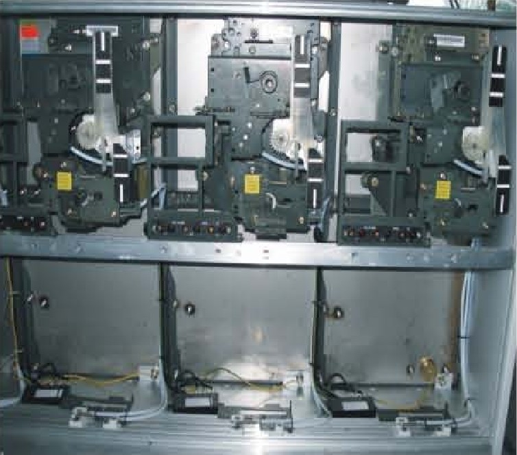
●操作机构室位于充气柜的上半部分,机构滚轴与开关操作盘紧配,并通过螺栓固定。
The operating mechanism chamber is located on the top half of cubicle, the rolling shaft of mechanism is matched tightly with switch operating plate and fixed by bolts.
●机构分单弹簧(进线机构)和双弹簧(出线机构)分别组成了环网回路和变压器回路开关,弹簧均为盘式弹簧,具有装配精度高、操作省力、寿命长、稳定性高的特点。
The operating mechanism which is of disk spring type with high assembly preesion and stability and with long service life and easy operation is divided into two types, the single spring using for ring net circuit (incomer unit) and double spring using for transformer circuit (outgoing unit).
熔断器室 Fuse chamber
●熔断器室(熔断器密封仓)位于柜体中部,置于充满SF6气体的气箱中。 熔断器密封仓由采用APG工艺浇注的环氧树脂绝缘筒及上导电极和下导电极(端盖)组成。前门上有熔断器动作指示器,方便观察和维护。用操作手柄拧开可方便更换熔断器。
Fuse chamber (fuse silo), consisting of epoxy resin insulation barrels casted by APG technology and upper and nether conductors (cover), is located in middle of cubicle and built in SF6 gas filled tank. There are melt indicators of fuse on the front door for easy checking and maintaining. The operating handle can be used for replacing the fuse body after unscrewing the covers.
电缆室 Cable chamber

●柜内电缆安装空间宽裕,电缆连接高度约600mm,每单元的电缆室之间用敷铝锌板隔开,便于维护和检修。剩余的大部分空间可装电流互感器及其它控制保护器件。
The cable chamber of cubicle is big enough for fitting cable, the connection height of cable can reach over 600mm, except the cable, the rest space can be use to fit the CT or other control and protection components if any. The cable chamber of each unit is isolated by Aluzine steel sheet to convenience for checking or maintaining.
●电缆的连接采用预制式电缆插接件,插接件可选用屏蔽型、非屏蔽型,也可加装避雷器。
The prefabrictad cable inserters, either shield type one or non-shield type one, are adopted for cable connections. The arresters can also be fitted here too.
●对于双电缆进线并加装避雷器,必须采用加深的电缆室盖板,电缆室的底部装有接地母排。
If double incoming cables and adding arresters, the deepening cable chamber cover should ba used. There is earthing busbars locating in the bottom of cable chamber.
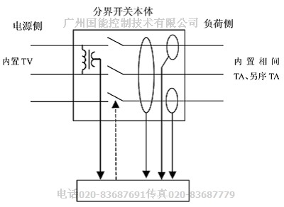
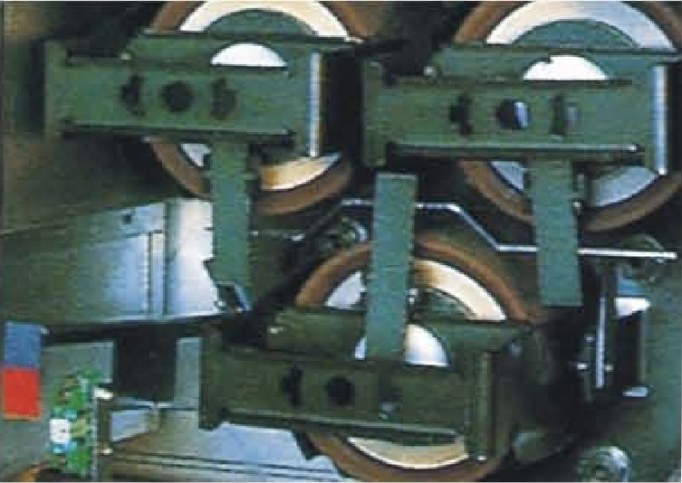
断路器本体 Vacuum circuit breaker
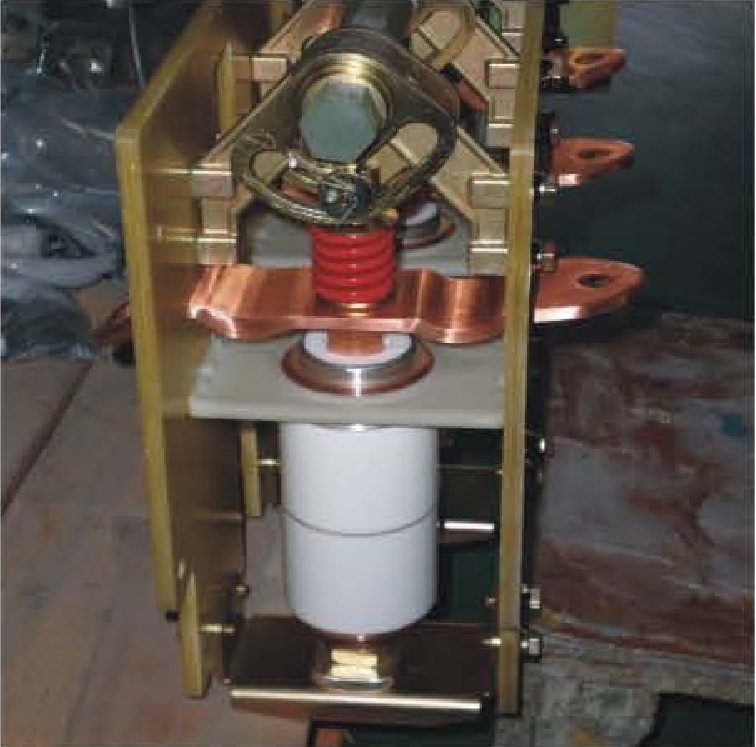
●单个传动密封口,减少漏气几率。
There is only one sealling driving to be used, it reduce the gas leakage probability.
●改变传统的绝缘方式,不用绝缘拉杆,传动轴采用强度高,绝缘性能好的材料制造。
The driving shaft of vacuum circuit breaker is made of excellent insulation material with high strength, it is no longer a traditional insulation pulling rod.
●可以开断大的短路电流,保护大容量的变压器。
The VCB inside has high capacity to break havy short circuit current, so can be used for protection of big size transformer.
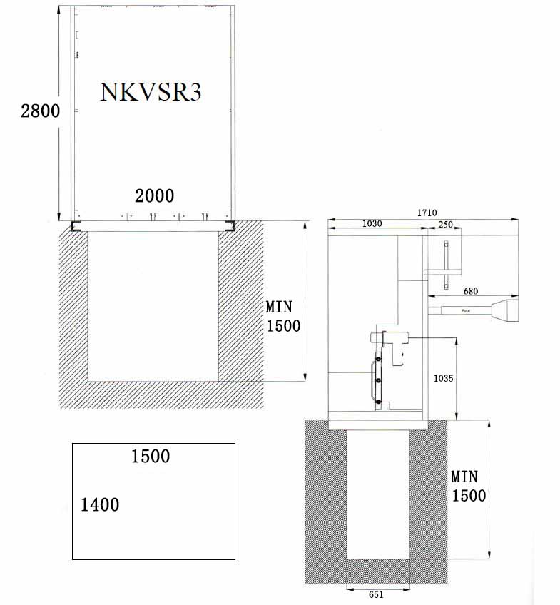
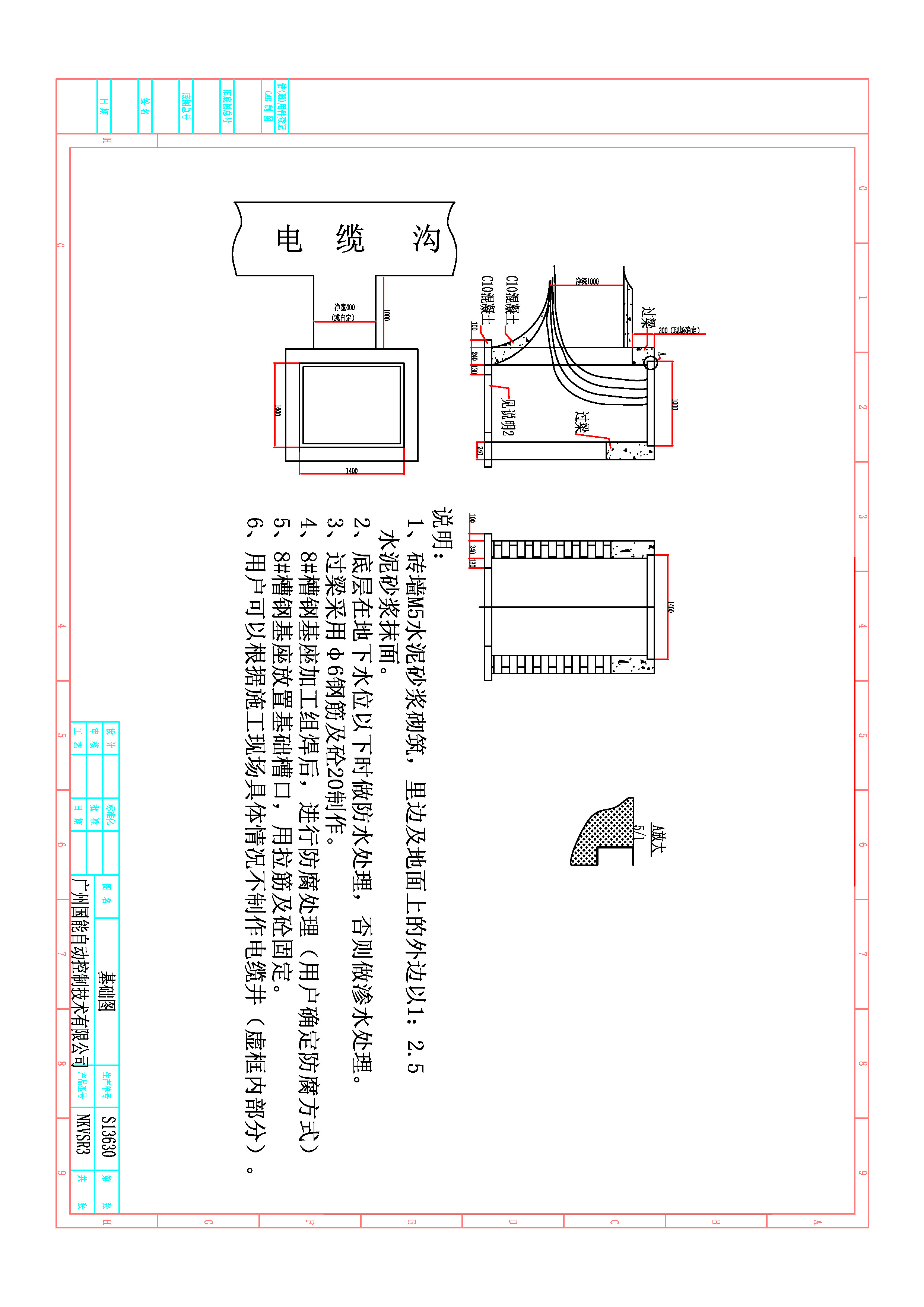
( 二) .3 安装及尺寸图Installation
●开关设备安装基础的施工应符合《电力建设施工及验收技术规范》中的有关条款规定
The foundation for cubicle should be in conformance with relative requirements stipulated in《The code of erection and
acceptance of electric power construction》
●柜体单列时,柜前走廊以1.5米为宜:双列布置时,柜间操作通道走廊以2米为宜
The corridor width in front of cubicles arranged in one row takes l.5m properly, and 2m proper for double rows arrangement
●一次电缆终端安装严格按相关工艺要求
The fitting of primary cable teerminals should be strictly according to relevant technology requirements
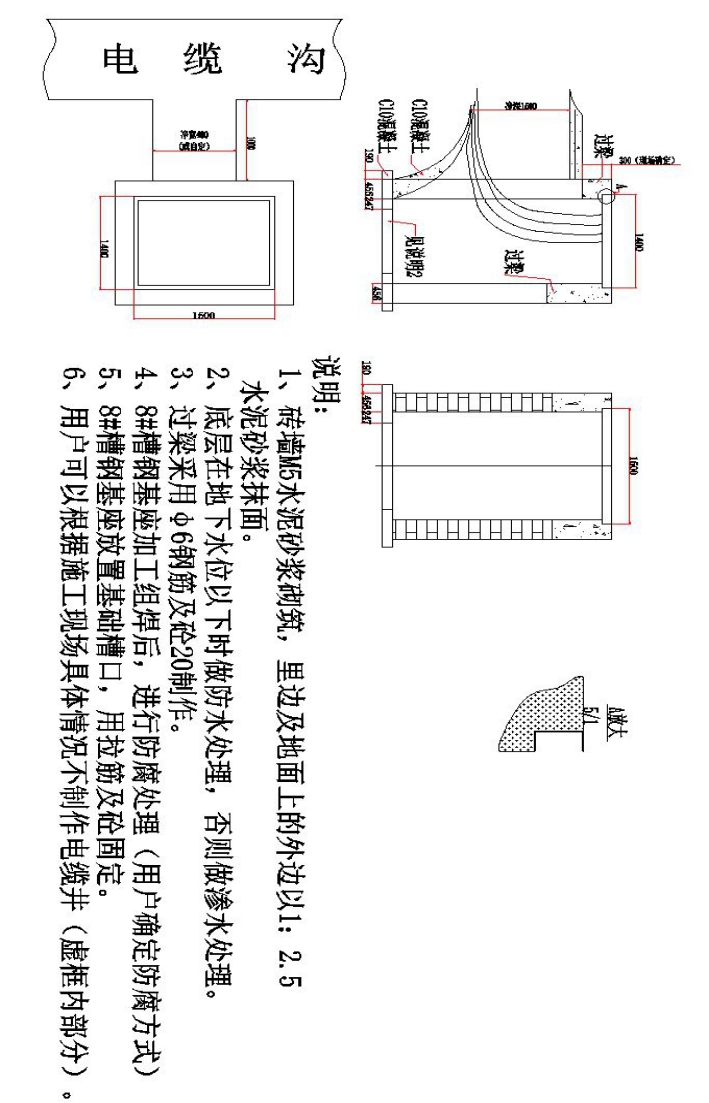
●电缆沟上方预埋10号槽钢,柜子放在槽钢上固定
The No. 10 U steels built in the top edges of cable trench can be used as the base of cubicle
订货时需确定的资料内容 The data needed for order
●一次线路系统图,排列图及平面布置图
Primary schame and the layout or the arrangement sketch.
●二次线路原理图,其中包括操作、信号、保护回路各电器元件的型号规格
Principle diagram of secondary circuit, including the type and the spec of electric components in operation, signal and
protection circuit.
●开关柜内电器元件的型号、规格、数量
The type, specification and quantity of primary components in the cubicle
●特殊环境条件下的要求
Special ambient condition
●附件及备件的种类和数量
The sorts and the quantity of accessories and spare parts.
●用户需要的特殊要求,订货时可以与制造厂协商
For special requirement, if any, please contact the manufacturer
整体安装
产品在安装前要先检查产品前要先检查产品铭牌、 合格证是否与订货单相符,装箱单是否与实物相符。确 认无误后再清理表面灰尘污垢,然后观察产品的分合指 示是否指示正常,箱体是否变形等,然后装上手动储能 手柄先进行5次手动分合操作,再进行5次电动分合操 作。机械动作正常后,进行10kv/1 min工频耐压试验。其他试验根据用户实际情况,选择性进行,如:电压、电流互感器精度、极性及变比试验。检查完毕后即可安装。
产品安装过程中,不得翻转、倾斜,并要求采取防震措施。起吊时水平吊起。
NKVSR3-10kV 单回路分界断路器开闭所

NKVSR3其他主要方案和外形尺寸 The main schemes and outline demensions
(一个气箱内可最大配置6个单元,可根据用户要求进行左右两侧扩展。)
12kV 单间隔柜体尺寸 宽325mm 深751mm高 1336mm
24kV 单间隔柜体尺寸 宽500mm 深751mm高 1336mm
35kV /T630A/单间隔柜体尺寸 宽600mm 深1030mm高 1800mm
35kV /T1250A单间隔柜体尺寸 宽600mm 深1500mm高 2445mm
35kV /T2500A单间隔柜体尺寸 宽800mm 深2100mm高 2650mm
备注 顶部/左侧/右侧增加PT,电缆接头,仪表箱,按需要增加尺寸,24kV/35kV地基图及安装图要根据合同图纸来设计
NKVSR3-40.5kV /630A分界断路器开闭所